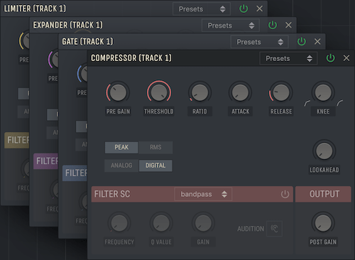
Dynamics Common Features
With ‘Dynamics’ we refer to the four Premium devices Compressor, Limiter, Gate and Expander. Below we explain the common features shared between them before moving on to the individual devices. With ‘detector’ or ‘detector signal’ we refer to the signal used to trigger the processing within the device.

PRE GAIN:
Changes the level of the input signal, which is the audio signal coming into the device.
POST GAIN
Changes the level of the output signal, which is the processed audio signal coming out of the device.
ATTACK
Set the time it takes for the detector to react to incoming audio signals. When the value is large, brief increases in audio levels are less likely to engage processing.
RELEASE
Set the time it takes for the detector to release incoming audio signals. When the value is large, brief decreases in loudness are less likely to disengage processing.
LOOKAHEAD
Delays the input signal in time relative to the detector signal. This allows dynamic range processing to be applied to transients that would otherwise pass through unchanged due to smoothing time of the detector.
PEAK & RMS MODES
Determines how the detector reacts to incoming audio signals. In Peak mode the detector is more responsive to changes in the input signal, allowing for rapid processing. In RMS mode the detector instead reacts to an average level of the input signal and is therefore less responsive to changes, which leads to less rapid processing.
ANALOG & DIGITAL MODES
Impacts the behavior of how signals are detected and processed. In Analog mode the detector signal is more smooth and slower to respond. While in Digital mode the detector signal is less smooth and instead faster to respond.
FILTER SC
When Filter Side-Chain is activated a filter is applied to the detector signal. When applied it changes the behavior of the detection, and processing is based on the magnitude of frequencies within the filter range.
/manual/dynamics_filtersc.png
FILTER MODES
Determines wether the filter applied to the signal is a bandpass, lowpass or a highpass. Each filter is useful depending on what range of frequencies you want to trigger the dynamic range processing with.
FREQUENCY
Determines the cutoff point for the lowpass and highpass filters. While for bandpass it determines the center frequency, or focus area, of the applied filter.
Q VALUE
Determines the ‘Q’ or resonance of the filter at the chosen frequency value.
GAIN
Changes the level of the filtered signal used for detection.
Audition
Enable the audition function to listen to the filtered signal being used for detection. This makes it easier to tune the filter parameters.

